The Synth Engine
The C15's first synthesis engine is named "Phase 22". The following block diagramm shows its components and signal flow. Please note that two levels of detail are available.

Design Concepts
The design goal for Phase 22 was to take advantage of digital synthesis algorithms in order to build an expressively playable instrument that has a strong individual character. At the same time the set of parameters should be small enough to be easily accessible.
The core structure is a phase modulation synth that is based on two sine oscillators and two sine shapers only. Their signals can be passed through a comb filter, a state-variable filter, and a chain of five effects.
The Comb Filter is a tool for complex spectral shaping and also works as a resonator. The State Variable Filter can be applied flexibly for subtractive filtering.
The signal routing is determined by the settings of the Output Mixer and the Feed- back Mixer. The feedback bus can be used to create feedback loops between different function blocks.
The filters and effects have an important influence on the feedback behavior: their amplitude and phase responses determine the frequencies where the feedback can result in self oscillation.
Background
For more background on the synthesis engine, please
read here
The Components in Detail
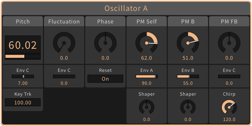
Oscillator A, B
The two sine wave oscillators are the only signal sources. With a random frequency fluctuation they can also produce tunable noise. They are equipped with three phase modulation inputs for:
- self modulation
- modulation from the other oscillator
- modulation from the feedback (FB) signal
Here you see the oscillator signal for different amounts of self modulation and here various oscillator fluctuation spectra.
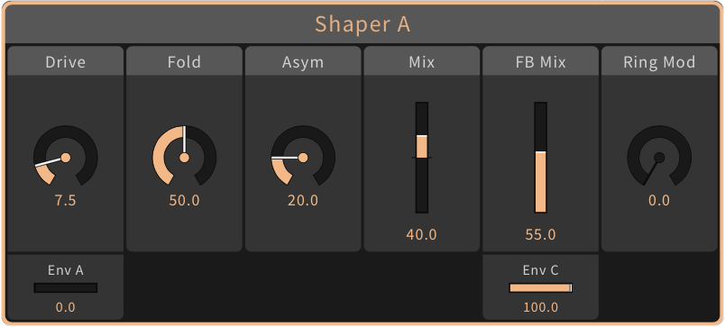
Shaper A, B
The signal of each oscillator can be processed by a wave shaper. The shaping curve is a sine function with adjustable foldback and asymmetry. The mix amounts of the shaper signal can be adjusted individually for each phase modulation branch and for the output.
The Shaper block also contains mixing points for the feedback signal and the result of a ring modulation between the output signals of the branches A and B.
These diagrams show the output signal depending on Drive, Fold and Asymmetry.
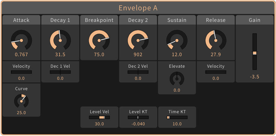

Envelope A, B
These two ADBDSR envelopes are the control sources for:
- the output amplitude of the Oscillator-Shaper branch
- the Oscillators' phase modulation depths
- the Drive (input gain) of the referring Shaper
There is detailed control of how the velocities and the key position influence levels and times.
This diagram shows the segments of the envelopes and here you see some typical applications.
Envelope C
The third ADBDSR envelope has bipolar Breakpoint and Sustain levels. Depending on the Loop parameter it can repeat the D1 and D2 segments, oscillating between the Breakpoint level and the Sustain level. Envelope C can modulate:
- the pitches and fluctuations of Oscillator A and B
- the feedback signal
- parameters of the Comb Filter and the State Variable Filter
This diagram shows possible shapes of Envelope C.
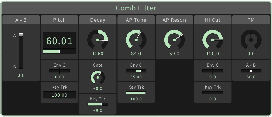
Comb Filter
The Comb Filter contains:
- a precisely tunable delay (Pitch)
- a control for the Decay time of the impulse response
- a second-order Allpass (AP) filter
- a lowpass (Hi Cut) in the feedback loop
- a delay modulation by the Oscillator signals, similar to phase modulation (PM)
Here you see a block diagram of the Comb Filter and these graphs show two basic frequency responses.
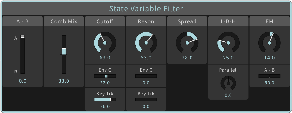
State Variable Filter
The State Variable Filter has a variable 4-pole structure with:
- two internal 2-pole filters with splittable cutoff frequencies (Spread)
- crossfade between serial and parallel modes
- crossfade between lowpass, bandpass, and highpass mode
- cutoff frequency modulation (FM) by the Oscillator signals
Here you see a block diagram of the State Variable Filter. Additional graphs show the frequency responses in serial and parallel mode.
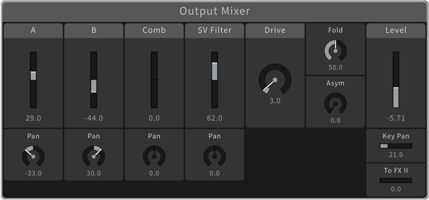
Output Mixer
The Output Mixer creates a stereo sum of the signals from Oscillator/Shaper A and B, the Comb Filter and the State Variable Filter. It includes a sine shaper for the sum signal of each voice.
This diagram shows the signal flow of the Output Mixer.
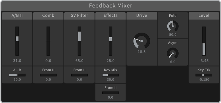
Feedback Mixer
This mixer combines the following signals for the feedback bus: the outputs of the Comb Filter and the State Variable Filter and the output of the Effects chain, with a separately adjustable amount of Reverb. It includes a sine shaper for the sum signal.
The feedback bus signal (FB) can be used for the phase modulation of the Oscillators and it can be injected into the signal path behind the Shapers for direct audio feedback.
In Layer Sounds the Feedback Mixer can route signals between the layered voices. It provides an additional input for the Oscillator signals (A/B) of the other Part, and the Comb, SV Filter and Effects channels can also receive signals of the other Part.
This diagram shows the signal flow of the Feedback Mixer.
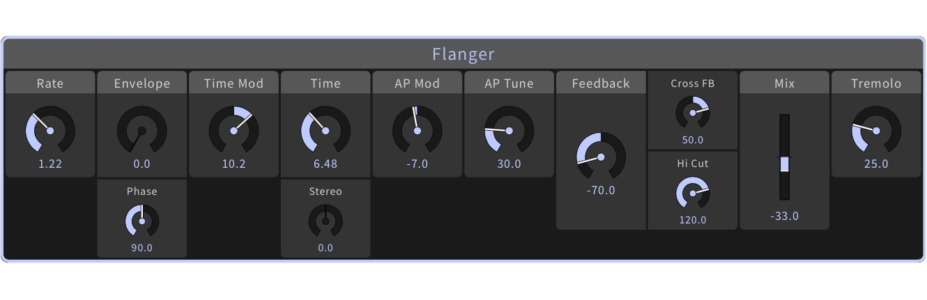
Flanger
An LFO-modulated stereo delay plus a 4-pole allpass filter creating a wide range of chorus, flanger and phaser effects. The LFO can also modulate the amplitudes of the output signals for a tremolo effect.
This diagram shows the signal flow of the Flanger.
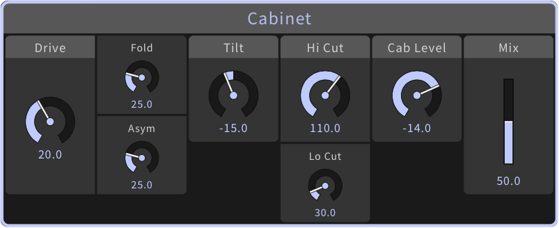
Cabinet
A stereo distortion unit (sine shaper) with pre and post filtering that can sound similar to a guitar amp driving a speaker.
This diagram shows the signal flow of the Cabinet.
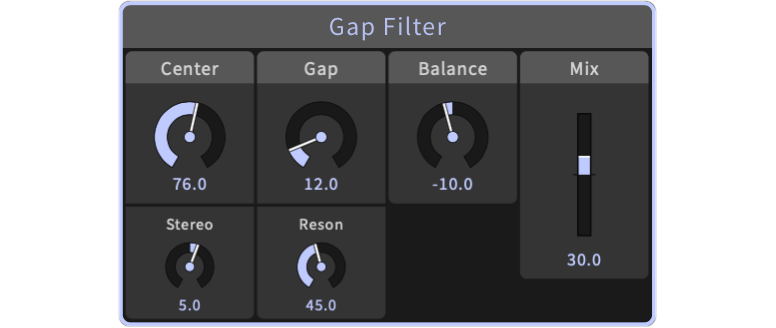
Gap Filter
A 4-pole lowpass and a 4-pole highpass in a parallel or serial structure, creating a flexible band-rejection or band-pass filter. The offset between the center frequencies of the left and the right channel can be controlled.
This diagram shows the signal flow of the Gap Filter and here you see some of its frequency responses.
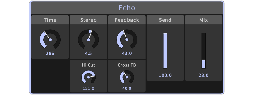
Echo
A stereo delay effect with adjustable cross-feedback.
This diagram shows the signal flow of the Echo.
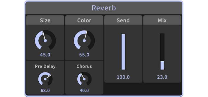
Reverb
A flexible simulation of rooms and halls. The Size can be varied without artefacts.
This diagram shows the signal flow of the Reverb.
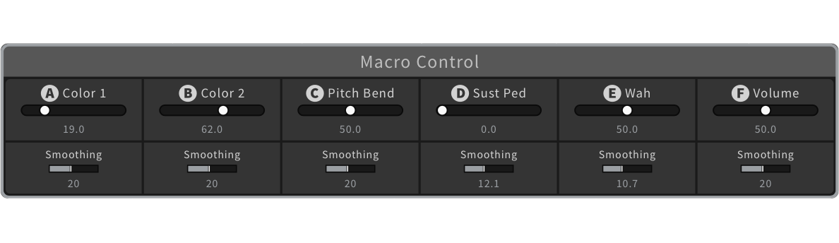
Macro Controls
Six Macro Controls (A, B, C, D, E, F) are available as modulation sources. 106 parameters can be assigned as modulation targets with individual amounts. For each Macro Control a Smoothing time can be set.
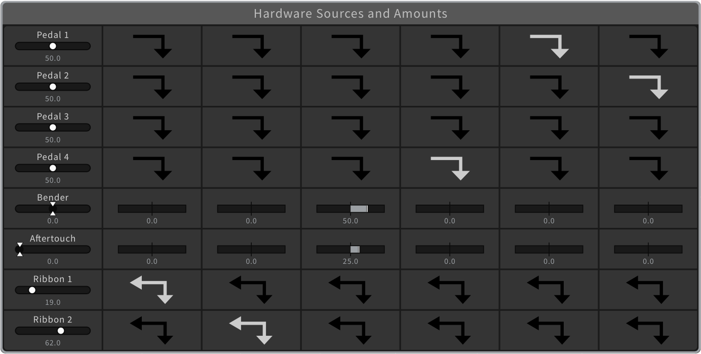
Hardware Sources
Eight physical control elements are available, that can be mapped to the six Macro Controls:
- four Pedals
- two Ribbons
- the Bender
- Aftertouch
This illustration shows how the modulation works.
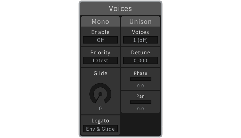
Voices
The parameters in this group control the monophonic mode and the use of the voices for Unison.
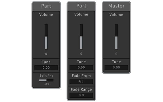
Part and Master
Master Volume and Master Tune are always available, while the Part groups are used to control aspects of the two Parts of a Split Sound or a Layer Sound.
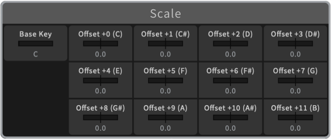
Scale
The Scale group offers twelve Offsets to tune the keys of an octave. The Base parameter can be used to shift the base key of the scale.
This diagram shows an equal-temperament scale and the available tuning range, and this diagram shows a scale where four keys have been micro-tuned.


